In Studio II, skills and subjects introduced in Studio I are further explored by engaging design problems and by investigating more complex problems, including language and elements. During this studio, White delved into wood joinery across different scales, a precedent study to remake the drawings and to propose a new design feature, and finally created a design proposal for two different study structures.
Studio II
Spring 2020


In Studio II, we explored how different parts can be held together through joinery. For this project, we were required to create three small wooden models with joints holding each model in place. After completing the three iterations, orthographic drawings of the models and joints were made.
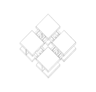
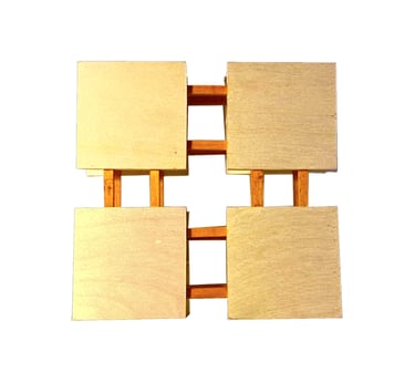
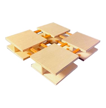
The first iteration model was derived from a section of a typical floor joist. We took this section and created the first iteration by duplicating the piece four times. In the model, there are sixteen dowel joints holding all four sections of the design, and four tongue and groove joints for the top and bottom to slide into place.
Joinery Model I

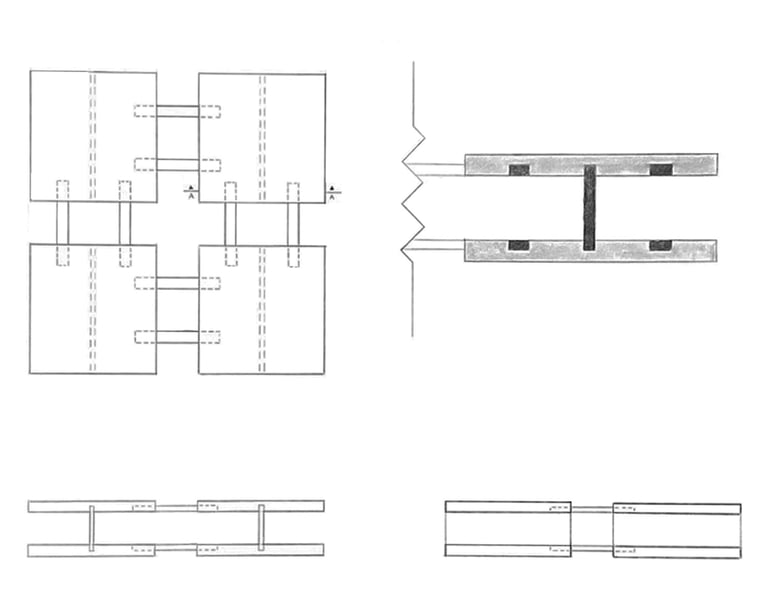

Top View
Section A-A
Front View
Right View

Axonometric View
Iteration I Model
Charcoal Drawing
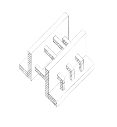

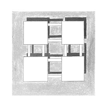
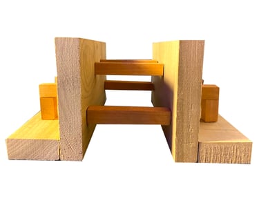
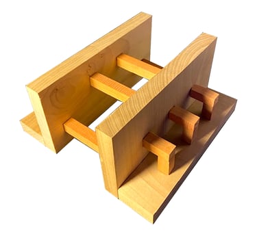
The second iteration joint model incorporates two large extruded “L” shapes derived from the original joint model of the floor joist. This model contains twenty mortise and tenon joints to hold both sides and the outer pieces together.
Joinery Model II


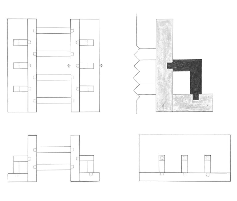

Top View
Front View
Right View
Section A-A
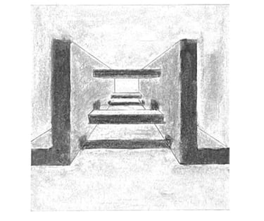

Iteration II Model
Charcoal Drawing
Axonometric View
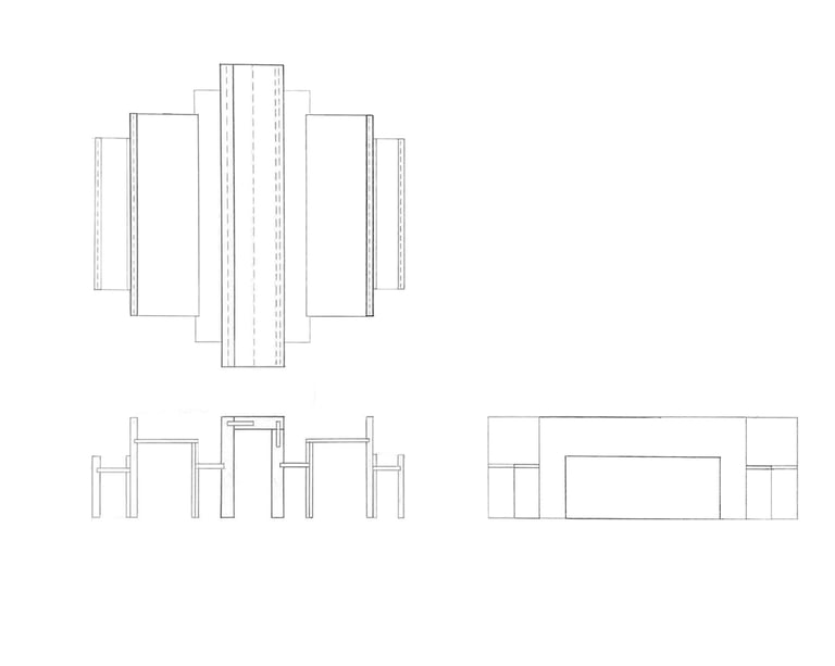

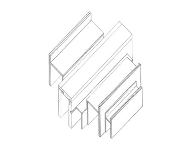

The third iteration joint model is designed with elements from the previous iterations but created into what could be seen as a space. This design resembles a series of closely situated buildings you might see in a city or a small town. The model contains two spline joints and six tongue and groove joints.
Joinery Model III
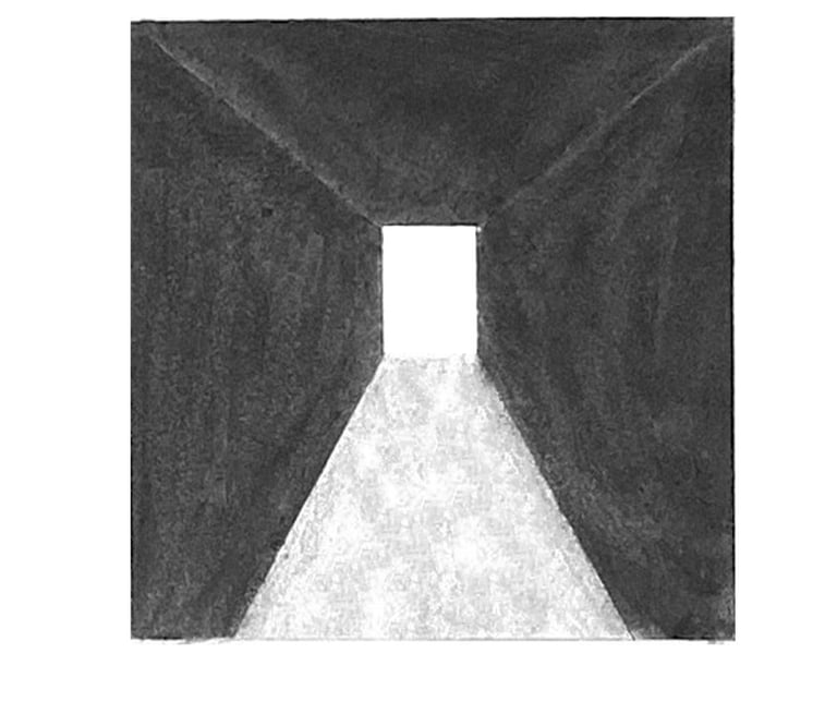

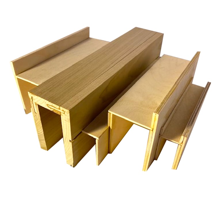

Iteration III Model
Charcoal Drawing
Top View
Front View
Right View
Axonometric View
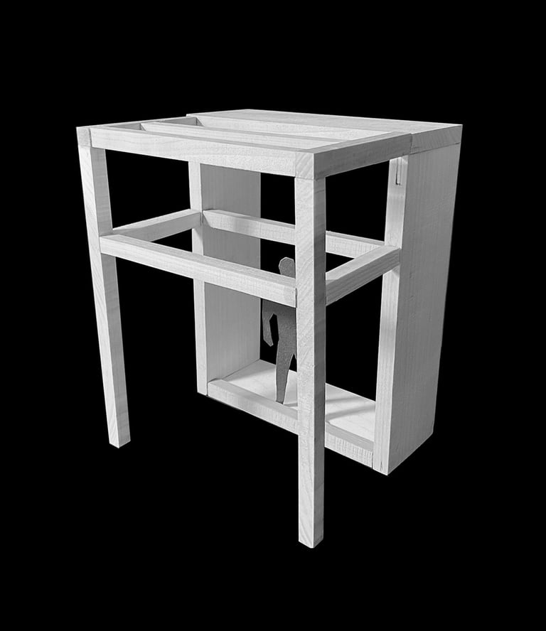

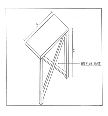

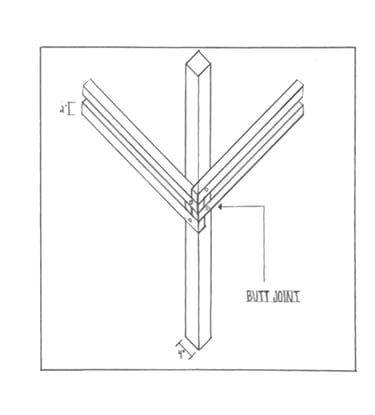

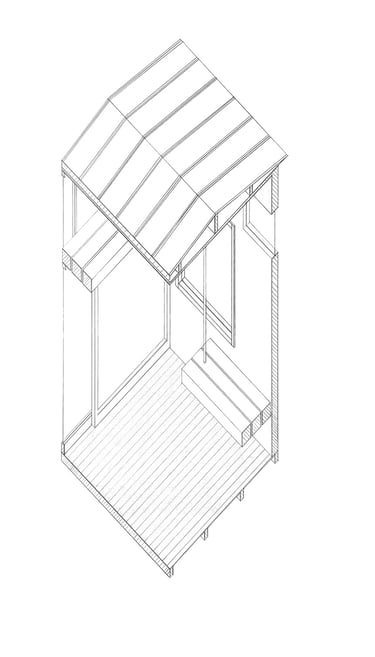
In Studio II, we explored a precedent of a small structure named Lyset Paa Lista, located in the sand dunes of Lista, Norway. This three-week project was undertaken by architecture students from Norway and Mexico. Named after the unique natural light in the area, the project aimed to showcase the natural beauty of the land and encourage migration.
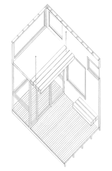
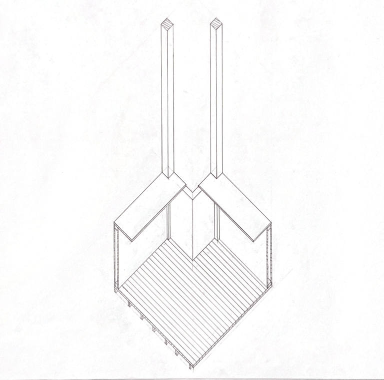
After researching and understanding Lyset Paa Lista's structure, orthographic drawings were produced. Additionally, an axonometric view of a section of the structure was drawn, focusing not only on the overall design but also on the joints within.
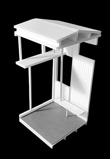
Following the study of Lyset Paa Lista, we were tasked with adding an alteration to the structure. The chosen alteration was a loft area above the back porch, providing a scenic overlook of the sand dunes and increasing the internal space. The alteration model incorporated elements defining the spatial characteristics of the structure, including the new loft space.
Building on lessons learned from the previous project, we emphasized the importance of joints in holding different parts together. Applying this knowledge to the precedent study, we analyzed the various joints used in Lyset Paa Lista and how they contributed to structural integrity.
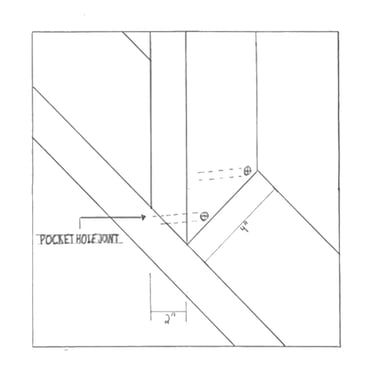
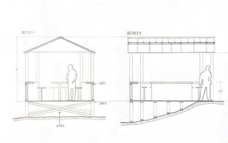
Lyset Paa Lista features three types of joints. The first, known as half lap joints (Joint A), is used by diagonal wooden beams below the structure, overlapping and reinforced together with wood screws. The second joint (Joint B), termed butt joints, is prevalent throughout the structure, where perpendicular elements meet and are reinforced with wood screws at a 90-degree angle. The final joint in the structure (Joint C) is the pocket hole joint, utilized for framing when perpendicular elements meet at a 45-degree angle, where wooden screws alone cannot provide sufficient reinforcement.
Lyset Paa Lista Exploration
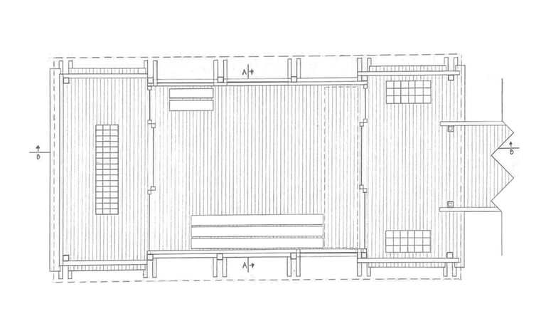

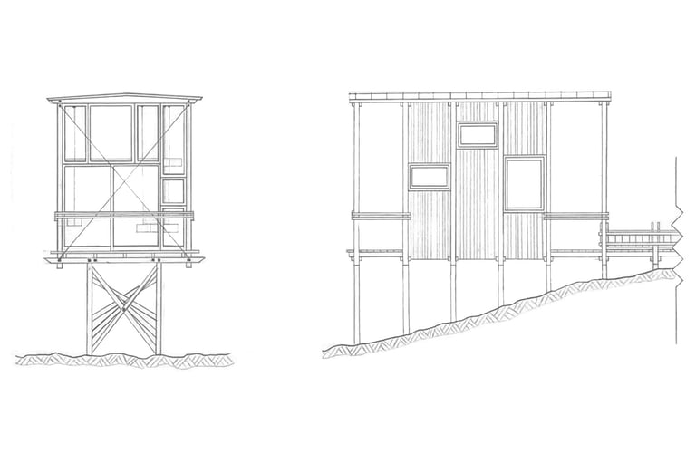

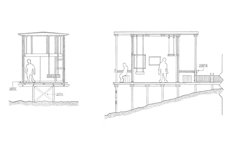





Section Model
Alteration Model
Joint A
Joint B
Joint C
Section A-A
Section B-B
Axonometric Section with Alteration Design
Front Elevation
Right Elevation
Axonometric Section
Floor Plan
By Tyin Architects
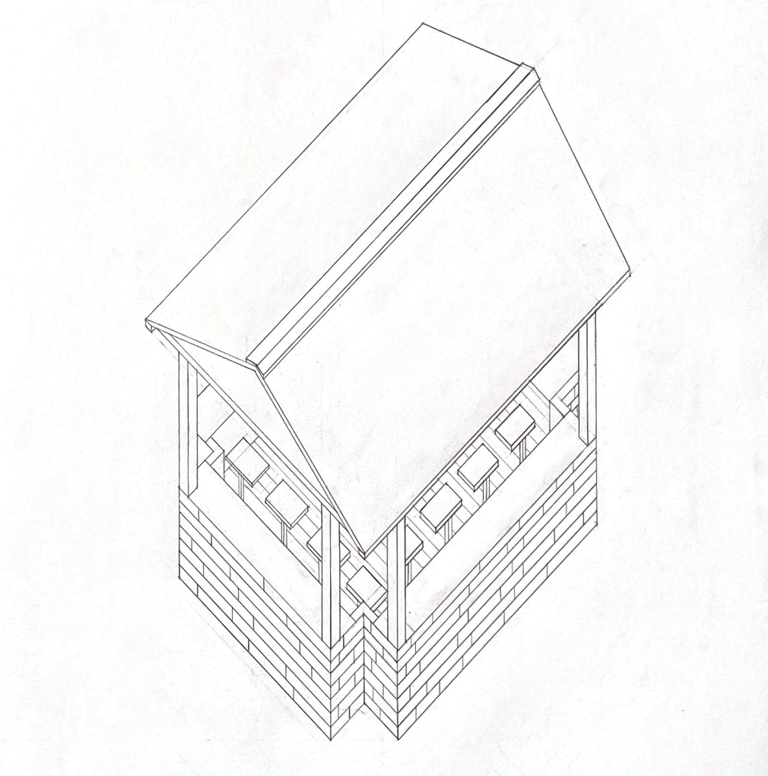

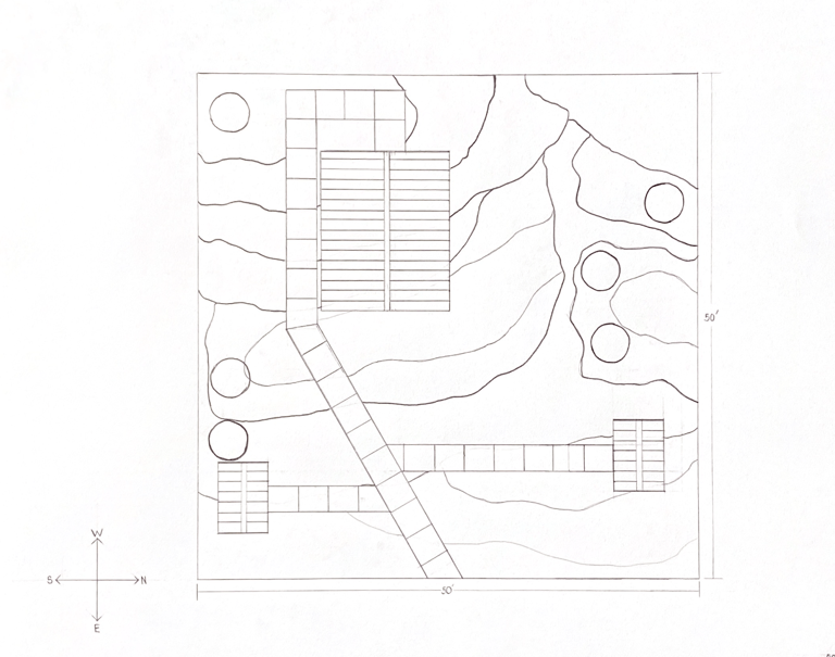

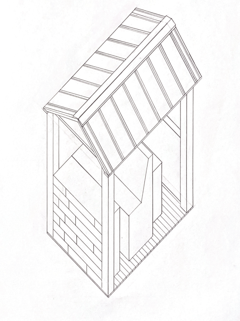
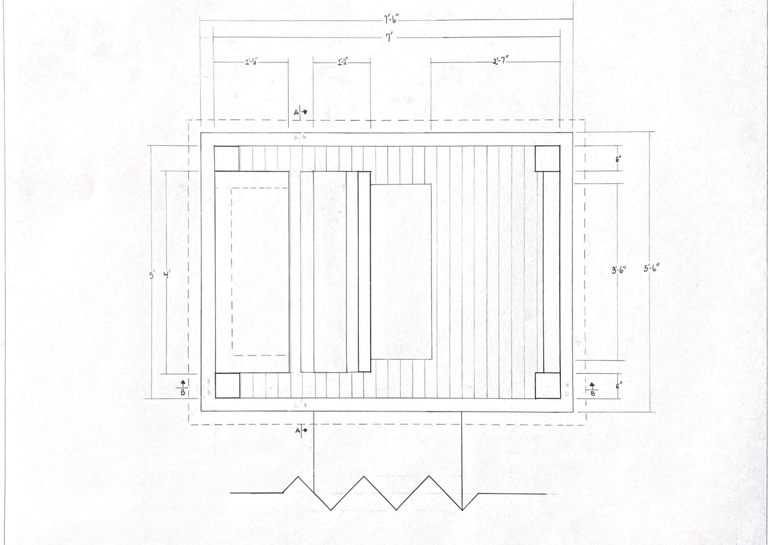
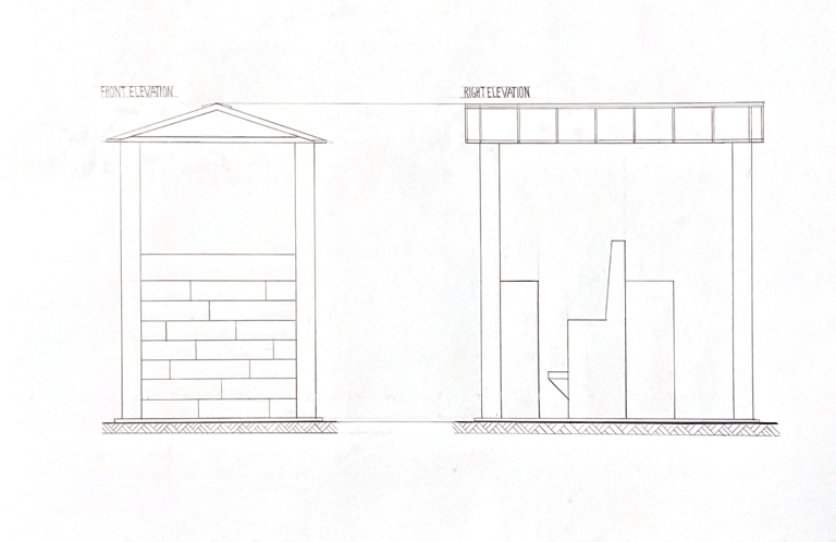
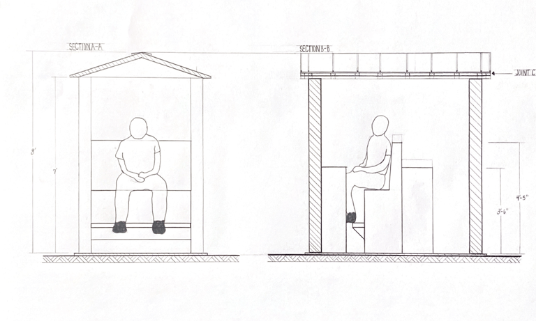
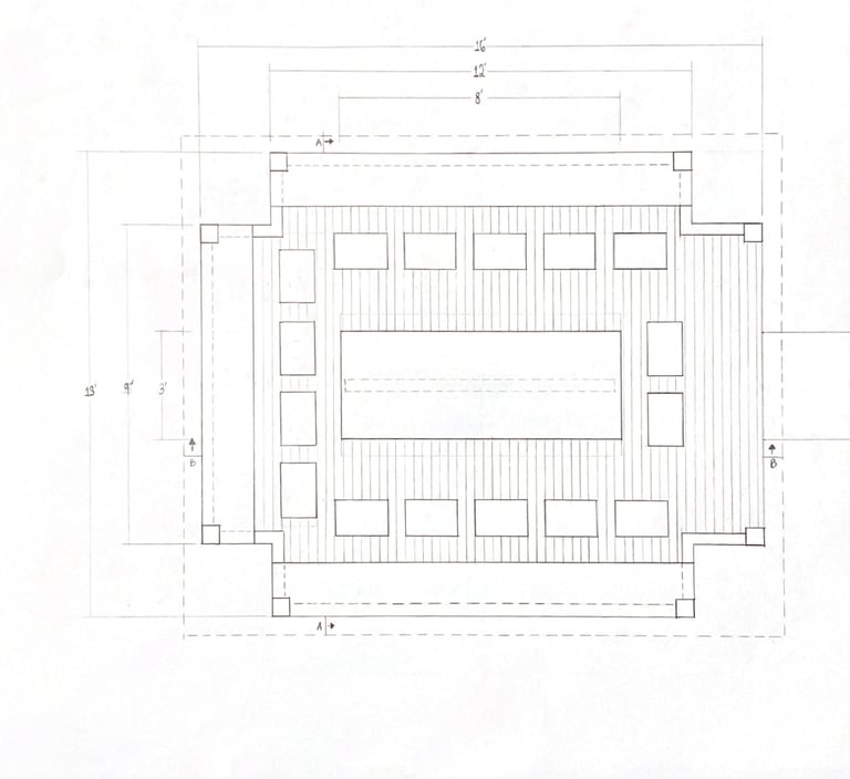
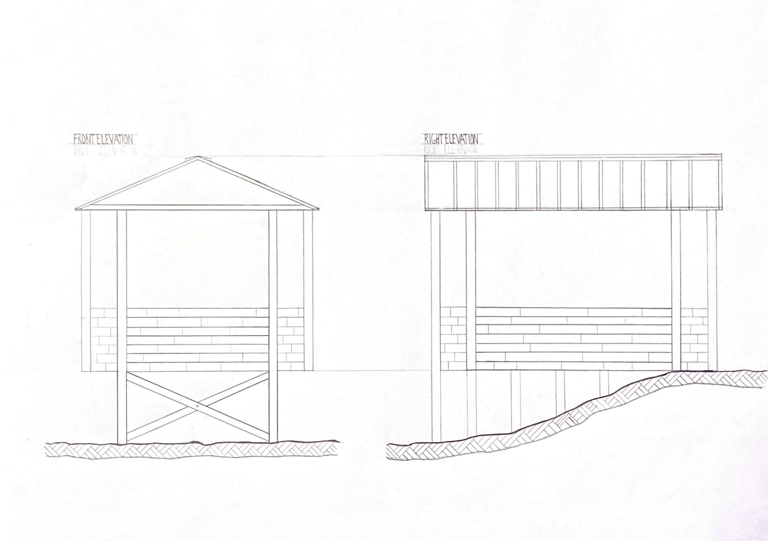
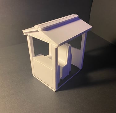
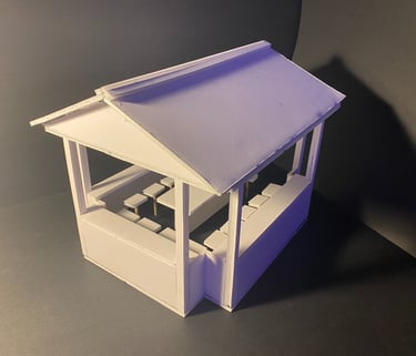
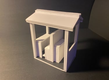
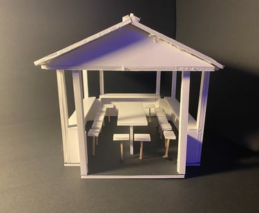
Similar to Studio I’s Study Pods, Studio II delved into more study areas. Given a site on the Marietta Campus nestled within the woods, three study areas were created. Two of these areas serve as small, individual study areas for students, each equipped with a seat, a countertop, and storage for belongings. The third area is a large study area designed for groups, accommodating sixteen seats centered around a table with additional countertop space along the edges. The simple design of these three structures aligns with the overarching goal of providing a variety of study spaces for students, all nestled within the campus woods.
Study Pods Part II








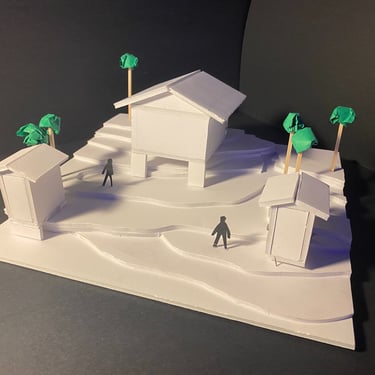

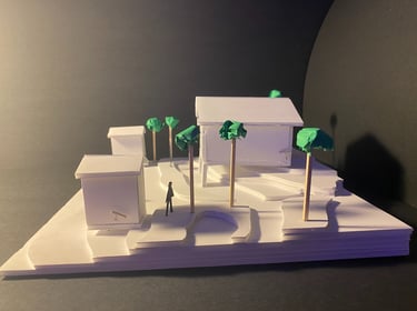





Site Model
Small Study Pod Model
Large Study Pod Model
Section A-A
Section B-B
Axonometric Section
Front Elevation
Right Elevation
Axonometric View
Floor Plan
Section A-A
Section B-B
Axonometric View
Floor Plan
Right Elevation
Site Plan
Front Elevation
Small Study Pod
Large Study Pod


